Stock Skid Unit Available Now.
Give Us A Call For More Information, (800) 628-6233
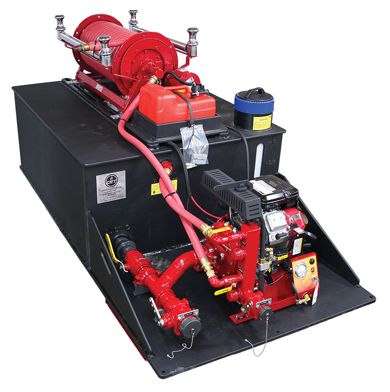
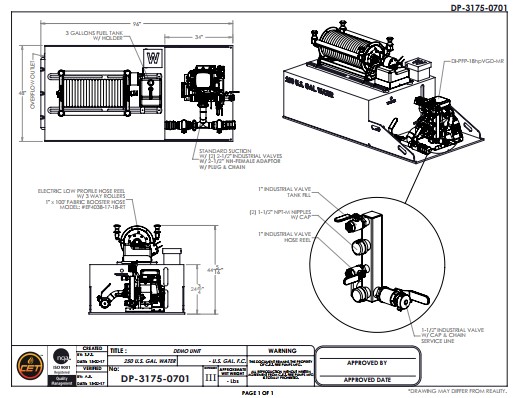
CET Custom Built Skid Unit
- 250 Gallon Water Tank
- CET Fire Pump
- V-Twin 20 HP Honda Engine
- 3 Gallon Fuel Tank
- Dual 2-1/2 in. Suctions
- 12 Volt Booster Reel
- 100 ft. of 1 in. Booster Hose
Skid Unit In Action
Custom Skid Unit Quote
Looking for a skid unit quote?
Use our Skid Unit Configuration Wizard below to design a custom skid unit to fit your needs. After completing all of the fields, click the submit button to forward your request to one of our service managers. Our service department will configure your skid unit as you requested and supply you with a quotation.
If you need a set of specifications or more details on the construction of our skid units they are included below. These specifications make it easy to prepare a bid for your custom skid unit. As always, if you have any questions please feel free to contact one of our friendly customer service representatives.

Skid Unit Specifications
All Firefighting Skid Units Include
Tank Color
The tank color will be black.
Tank Construction
The tank shall be constructed of ½ in. extruded U.V. stabilized high impact copolymer polypropylene (CPP). The material is ten times stronger than regular polypropylene. CPP, unlike steel, aluminum and fiberglass, offers a combination of outstanding physical, chemical, mechanical, thermal and electrical properties. CPP resists cracking, retains stiffness and flexibility, and has a far better impact strength in extreme cold temperatures than that of natural polypropylene. CPP is non-toxic, non-staining and easily fabricated. CPP is non-corrosive and lighter in weight than steel, aluminum, and fiberglass and is 100% recyclable.
Tank Baffles
The transverse partitions are constructed of 3/8 in. copolymer and the longitudinal is constructed of ½ in. Each baffle partition is one piece in design and extends from side to side and front to rear of the tank. These are placed to provide maximum flow, minimum surge, and comply with NFPA 1901.
Fill Tower
The fill tower shall be constructed of ½ in. copolymer material. The size shall be 8 in. high, 8 in. wide and 8 in. long. Its location shall be to the right side and rear corner unless otherwise specified by the customer. The floor of the fill tower shall be a perforated sheet (removable type screen) to prevent small objects from falling into the tank. The fill tower lid shall be mounted to allow air to escape when closed.
Overflow Provision
The overflow piping shall be 4 in. inner dimension. It shall be made of a minimum of schedule 40 copolymer pipe designed to run through the tank.
Tank Lid
The tank lid shall be constructed of ½ in. copolymer material with 2 in. diameter round bar stock, fitted and welded in such a way that will reinforce and add strength to the top of the tank. They shall extend up through the lid to a point even with the top walls of the tank. To insure maximum strength, lifting point are fitted into the internal structure, and welded on eight sides.
Venting
An air escape vent shall be installed inside the tank to allow maximum fill capacity should the vehicle be parked on unlevel ground. The piping shall be vented to the fill tower above the overflow level.
Tank Sump
The tank sump shall be constructed of ½ in. copolymer material. A recessed 3 in. schedule 160 threaded insert shall be welded to the sump for connection to the pump. An anti-swivel partition shall be installed directly above the sump to prevent water swirl from occurring during water draw.
Tank Fill
A 1 ½ in. schedule 160 coupling shall be installed at the front of the tank. There shall be a pressure deflector welded inside the tank. There shall be a pressure deflector welded inside the tank to deflect pressure away from baffle partitions.
Mounting and Structure
The tank shall be nitrogen welded to a 1 in. x 3 in. beam skid assembly fabricated of 1 in. thick polypropylene, U.V. stabilized. This skid is to be 90 in. long, 48 in. wide and includes a ½ in. thick polypropylene pump platform.
Sight Level Gauge
The tank shall have one liquid level sight gauge incorporated into the left rear tank wall facing the pump platform.
Control Panel
A control panel with an engine start button, and engine shut-off switch, a panel light and switch, a throttle control and a 2 ½ in. liquid filled discharge gauge shall be provided and conveniently located on pump/engine assembly.
Pump Primer
The pump shall be primed by a fast and simple to use exhaust primer and quarter turn bronze valve.
Piping
All piping shall be hot dipped galvanized pipe, or high-pressure, flexible type hose. All suction and discharge valves shall be easily accessible from the rear of the unit.
Valves and Hardware
There shall be an Akron 2 ½ in. tank-to-pump suction line with a 2 ½ in. quarter turn valve, in-line, at rear of the unit, with a chrome plated plug cap and chain.
Expert Installation
The entire unit will be expertly installed in the customer's chassis by trained professionals familiar with skid unit installations and properly wired to the chassis electrical system.


